Signal Generator using Adafruit SI5351 Clock Generator
34,The DDS and related clock generation circuitry has made possible high accuracy, broad-banded programmable VFO functionality for very little money.;Analogue Devices’ AD9850;series offer HF frequencies for about;€5. Higher frequencies can be had for not much more money, with the Silicon Labs SI570 with its near GHz maximum frequency offering the highest. I recently came across;an interesting little device from Adafruit. Again, from Silicon Labs, the SI5351;offers 3 independent clock outputs from a single 25MHz reference, programmable via i2c, a maximum frequency of 160MHz and all for less than;€10 shipped. I had to have one.
\nThe order, along with some of the other wonderful goodies from Adafruit arrived soon enough, and I got to work, first off getting the encoder knob working. The plan was to have a rotary encoder with push button for setting the freqeuncy, an i2c LCD for display, and the clockgen, all hanging off an Arduino… in this case, a Leonardo clone.
\n
\n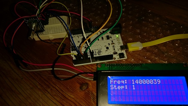 \n
\nThe sample code I first tried for the encoder worked ok, but then I found the builtin ‘encoder’ library, and tried that… far better, and no messing with interrupts.
\n
\nNext, I tried to get the display working… no joy using the standard LiquidCrystal_I2C library. I then ran an i2c scanner to find out if the device perhaps had a different address from standard. This gave me a ‘no devices’ error… something was wrong. After a bit more research, I discovered that the pins used for i2c on the Leo’ are not the same as on the Uno.;The Uno uses Analog pins 5 and 6 , whereas the Leo’ uses Digital pins 2 and 3. I reran the scanner, and it immediately detected the display on 0x27 ;and the clock-gen on 0x60. I plugged the address into some display testing code and had my display!
\n
\n
\nThe sample code I first tried for the encoder worked ok, but then I found the builtin ‘encoder’ library, and tried that… far better, and no messing with interrupts.
\n
\nNext, I tried to get the display working… no joy using the standard LiquidCrystal_I2C library. I then ran an i2c scanner to find out if the device perhaps had a different address from standard. This gave me a ‘no devices’ error… something was wrong. After a bit more research, I discovered that the pins used for i2c on the Leo’ are not the same as on the Uno.;The Uno uses Analog pins 5 and 6 , whereas the Leo’ uses Digital pins 2 and 3. I reran the scanner, and it immediately detected the display on 0x27 ;and the clock-gen on 0x60. I plugged the address into some display testing code and had my display!
\n \n
\nI then added in a few lines to include the Adafruit si5351 library and program one of the clocks to output 14Hz. I had my AOR8200 MkIII to hand, tuned to 14MHz AM so I hoped to be able to hear the clock on the AOR receiver. Nothing, however. A bit more reading, and I came across;another library for the SI5351… this one managing to avoid all the divider/multiplier calculations necessary with the Adafruit library. I modified the code once again to include this, and instead of doing any calculations, just wrote the required frequency directly to the clock. This time, I could hear a tone on the receiver. As I turned the encoder, the frequency on the display changed, and I could hear the tone get slightly higher in pitch… success by any measure.
\n
\nIt only remains to case this and use it to align a few projects.
\n
\n;
\n
\n
\n
\nI then added in a few lines to include the Adafruit si5351 library and program one of the clocks to output 14Hz. I had my AOR8200 MkIII to hand, tuned to 14MHz AM so I hoped to be able to hear the clock on the AOR receiver. Nothing, however. A bit more reading, and I came across;another library for the SI5351… this one managing to avoid all the divider/multiplier calculations necessary with the Adafruit library. I modified the code once again to include this, and instead of doing any calculations, just wrote the required frequency directly to the clock. This time, I could hear a tone on the receiver. As I turned the encoder, the frequency on the display changed, and I could hear the tone get slightly higher in pitch… success by any measure.
\n
\nIt only remains to case this and use it to align a few projects.
\n
\n;
\n
\n
| ; | \n\t\t|
| ; | \n\t\t\t#include <Wire.h> \n\t\t\t#include <LiquidCrystal_I2C.h> | \n\t\t
| ; | \n\t\t\t#include <Encoder.h> | \n\t\t
| ; | \n\t\t\t#include si5351.h | \n\t\t
| ; | \n\t\t\t; | \n\t\t
| ; | \n\t\t\tSi5351 clockgen; | \n\t\t
| ; | \n\t\t\t; | \n\t\t
| ; | \n\t\t\tconst int BUTTON = 8; | \n\t\t
| ; | \n\t\t\tlong oldPosition = -999; | \n\t\t
| ; | \n\t\t\tlong int step = 1; | \n\t\t
| ; | \n\t\t\tlong int frequency = 14000000; | \n\t\t
| ; | \n\t\t\t; | \n\t\t
| ; | \n\t\t\tEncoder myEnc(5, 6); | \n\t\t
| ; | \n\t\t\tLiquidCrystal_I2C lcd(0x27,20,4); //set the LCD address to 0x27 for a 16 chars and 2 line display | \n\t\t
| ; | \n\t\t\t; | \n\t\t
| ; | \n\t\t\tvoid setup () { | \n\t\t
| ; | \n\t\t\tlcd.init(); | \n\t\t
| ; | \n\t\t\tlcd.backlight(); | \n\t\t
| ; | \n\t\t\tlcd.setCursor(0, 0); | \n\t\t
| ; | \n\t\t\tlcd.print(Initialising…); | \n\t\t
| ; | \n\t\t\tclockgen.init(SI5351_CRYSTAL_LOAD_8PF); | \n\t\t
| ; | \n\t\t\tlcd.setCursor(0, 1); | \n\t\t
| ; | \n\t\t\tlcd.print(OK!); | \n\t\t
| ; | \n\t\t\tdelay (2000); | \n\t\t
| ; | \n\t\t\tpinMode (BUTTON, INPUT); | \n\t\t
| ; | \n\t\t\tdigitalWrite (BUTTON, HIGH); // Pull High Restance | \n\t\t
| ; | \n\t\t\tlcd.init(); | \n\t\t
| ; | \n\t\t\tlcd.backlight(); | \n\t\t
| ; | \n\t\t\tlcd.setCursor(0, 0); | \n\t\t
| ; | \n\t\t\tlcd.print(Freq: ); | \n\t\t
| ; | \n\t\t\tlcd.setCursor(6, 0); | \n\t\t
| ; | \n\t\t\tlcd.print(frequency); | \n\t\t
| ; | \n\t\t\tlcd.setCursor(0, 1); | \n\t\t
| ; | \n\t\t\tlcd.print(Step: ); | \n\t\t
| ; | \n\t\t\tlcd.setCursor(6, 1); | \n\t\t
| ; | \n\t\t\tlcd.print(step); | \n\t\t
| ; | \n\t\t\t// Set CLK0 to output 14 MHz with a fixed PLL frequency | \n\t\t
| ; | \n\t\t\tclockgen.set_pll(SI5351_PLL_FIXED, SI5351_PLLA); | \n\t\t
| ; | \n\t\t\tclockgen.set_freq(frequency, SI5351_PLL_FIXED, SI5351_CLK0); | \n\t\t
| ; | \n\t\t\t} | \n\t\t
| ; | \n\t\t\t; | \n\t\t
| ; | \n\t\t\tvoid loop () { | \n\t\t
| ; | \n\t\t\tint delta; | \n\t\t
| ; | \n\t\t\tif (!(digitalRead(BUTTON))) { | \n\t\t
| ; | \n\t\t\tif (step >= 1000000) | \n\t\t
| ; | \n\t\t\tstep = 1; | \n\t\t
| ; | \n\t\t\telse step = step * 10; | \n\t\t
| ; | \n\t\t\tlcd.setCursor(6, 1); | \n\t\t
| ; | \n\t\t\tlcd.print(step); | \n\t\t
| ; | \n\t\t\tlcd.setCursor(6+(step/10),1); | \n\t\t
| ; | \n\t\t\tlcd.print( ); | \n\t\t
| ; | \n\t\t\tdelay (200); | \n\t\t
| ; | \n\t\t\t} | \n\t\t
| ; | \n\t\t\tlong newPosition = myEnc.read(); | \n\t\t
| ; | \n\t\t\tif (newPosition != oldPosition) { | \n\t\t
| ; | \n\t\t\tdelta = newPosition > oldPosition? 1 : -1; | \n\t\t
| ; | \n\t\t\toldPosition = newPosition; | \n\t\t
| ; | \n\t\t\tfrequency = frequency + (delta * step); | \n\t\t
| ; | \n\t\t\tlcd.setCursor(6, 0); | \n\t\t
| ; | \n\t\t\tlcd.print(frequency); | \n\t\t
| ; | \n\t\t\tclockgen.set_freq(frequency, SI5351_PLL_FIXED, SI5351_CLK0); | \n\t\t
| ; | \n\t\t\t} | \n\t\t
| ; | \n\t\t\t} | \n\t\t