Building the PiDP8i
The story leading up to this can be read;here. In short though, I have always had a thing for retro computers, and DEC boxes in particular, and now I have a remake of a PDP8/I in the form of a kit provided by Oscar Vermeulen another retro computing geek with an excellent site at;Obsolescence Guaranteed.
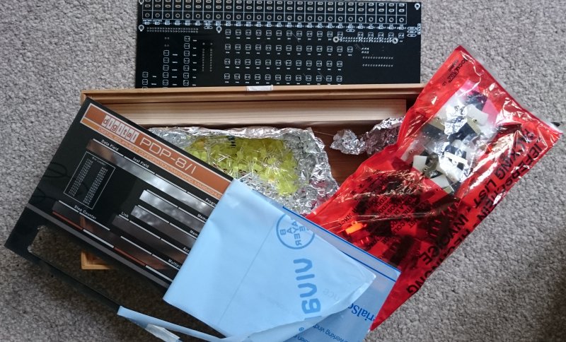
I finally received the kit, and once unboxed and inventoried, I referred to the build instructions on Oscar’s site, and to the PiDP8 Google Group, where other builders documented their experiences and build tips. The kit includes a perspex front panel with beautifully garish 60s graphics in orange and brown, a PCB on which all the various LEDs and switches are mounted along with the Raspberry Pi, which runs the simh emulator - the brain of the machine. It also includes a nice wooden - bamboo, I think - case for everything to live in when assembled.
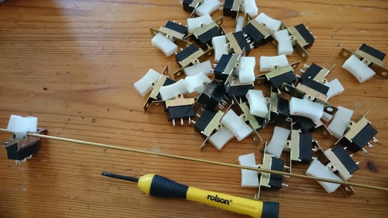 There are 26 switches on the front-panel to provide data-entry and run-control. These need to be soldered to the panel. When building the original series of prototypes, Oscar had a few small difficulties keeping the switches nicely aligned. A member of one of the Swiss hackerspaces suggested popping out the switch pivot and threading the switches en-masse onto an appropriately sized bar.;
Oscar provided a small brass bar, about 2mm in diameter for this purpose, and described how to cut and remove the pivot and use a screwdriver to keep the switch together while threading onto the bar.
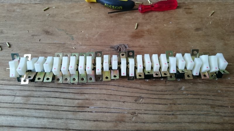 Rinse and repeat 26 times, and it’s done.;
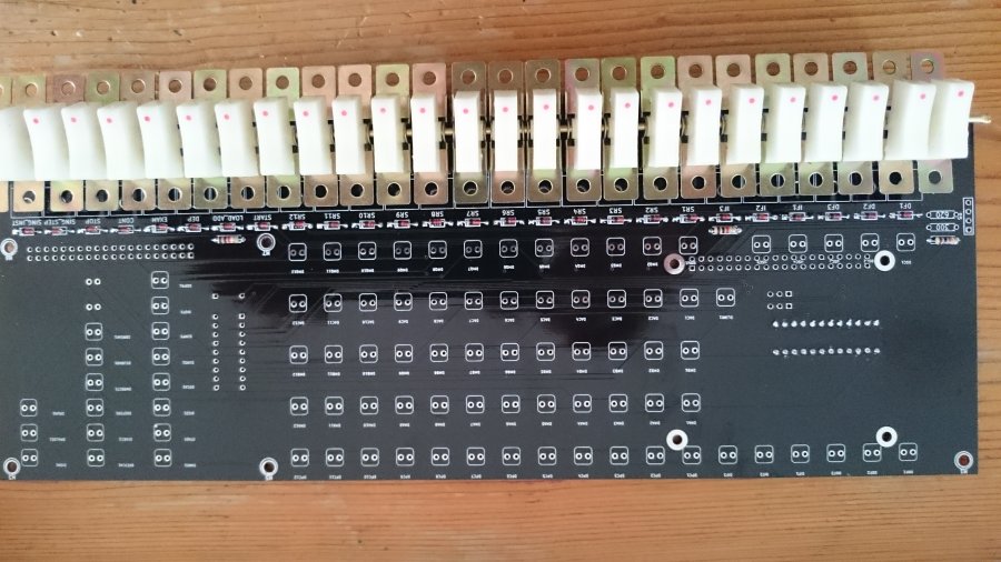
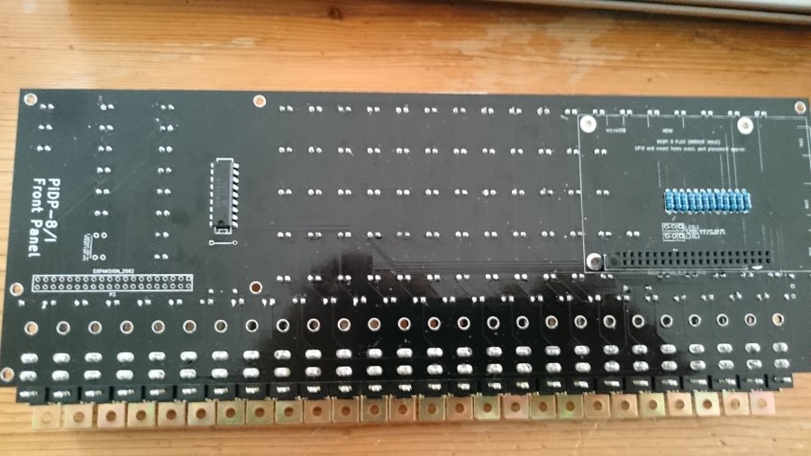
Once this was completed, the next job was to insert the terminals into the board and tack-solder the two end switches, Then, moving along from switch to switch, I;aligned each, ensured a close-fit and soldered. I did this slowly, and checked multiple times to ensure good alignment, and spacing. While not perfect, I am pretty happy with the result. I will mask up and paint later, when I get the correct type pf paint.
Rinse and repeat 26 times, and it’s done.;
Once this was completed, the next job was to insert the terminals into the board and tack-solder the two end switches, Then, moving along from switch to switch, I;aligned each, ensured a close-fit and soldered. I did this slowly, and checked multiple times to ensure good alignment, and spacing. While not perfect, I am pretty happy with the result. I will mask up and paint later, when I get the correct type pf paint.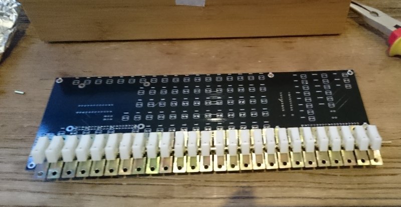 The next step was to solder in the rest of the components… first the diodes and resistors…
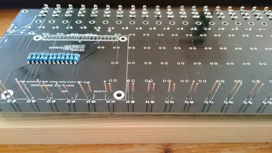
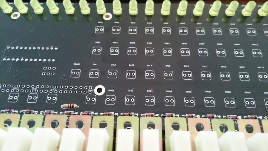
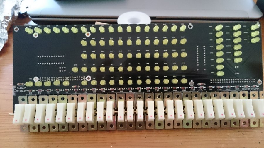
Then the LEDs… all 89 of them. There’s a trick to doing these right. They are the star of the show, after all, so it’s important to get them nicely aligned. My solution was to fit a row, supporting it from underneath with once of the blocks of wood that will eventually mount the PCB. I wasn’t too concerned about getting the alignment right initially… I tacked in one leg in each LED, then when a row was complete, held the board in one hand and re-melted the solder while pushing from underneath to ensure a nice flush-fit with the PCB.;
It didn’t take all that long, and the result looks nice…
The final few stages involved soldering in a driver IC for the LEDs and the 40way header that will accept the Pi’s GPIO pins.;
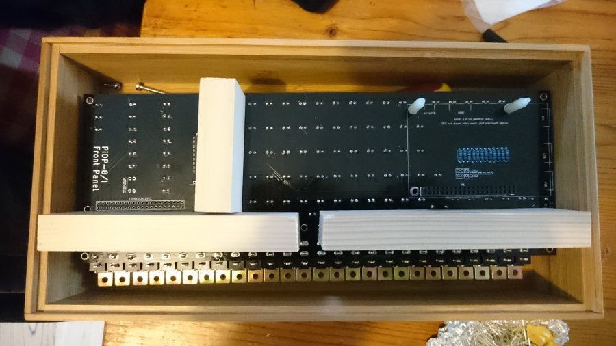
I then attached the wooden blocks that will support the PCB, and drilled the necessary holes in the back of the case to accept the screws and USB cable to supply power.
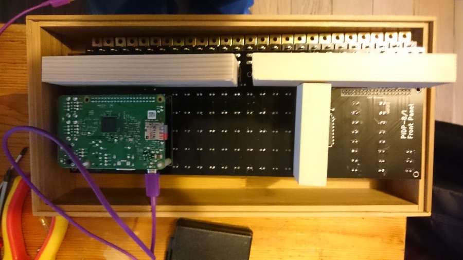
Pi fitted…
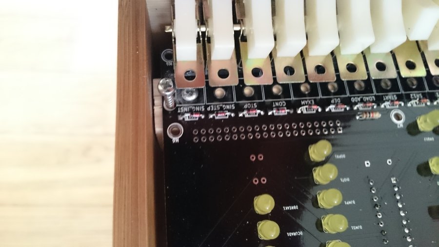
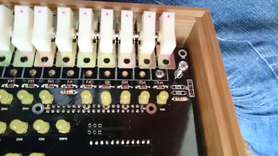
I drilled holes through the PCB to allow screws to be screwed in…;
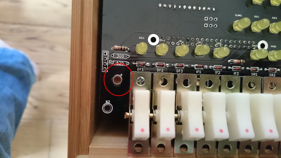
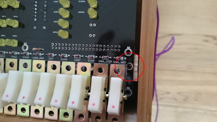
Then screwed in the screws… these will be used for the magnetic attachment of the front panel as suggested by;Chris Smith on the PiDP/8 Group.
Then glued two small magnets to the back of the panel, at the appropriate places…
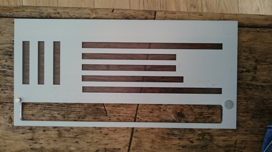
…and we’re done! Well, almost… I still need to get paint and paint the switches, but it works.
