Converting Suncom SFS Throttle to USB
Having been emboldened by a successful;conversion of my Thrustmaster F22 Flight Stick, I decided to try to capture all of the buttons on throttle too. A job that worked out easier than I expected as it turned out.
I came across;this page, where a conversion was described. However, this conversion relied on a custom PCB and a SMD PIC which had to be soldered. I have had mixed results in soldering SMD devices with small leg-pitch, so wanted to avoid this route if possible. The author did, however, provide a wiring diagram for the buttons. They are basically wired in a diode-matrix, albeit not on an actual matrix. 3 SELect lines and 8 read lines gives a maximum of 24 buttons. There are actually 18, but since the F22 has 18 already used out of a possible maximum of 32 (DirectPlay controller limitation) we have 14 to play with. Still not terrible.
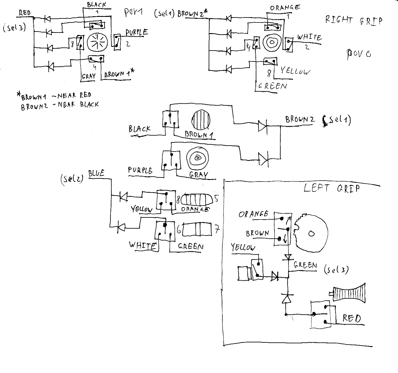 (thanks Shai Seger for the drawing)
Since the left and right throttles have their own set of buttons, I doubled up one of the SEL lines on the left with one on the right, and the 4 read lines with 4 from the right also, making sure that there were no overlaps.
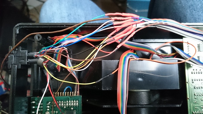
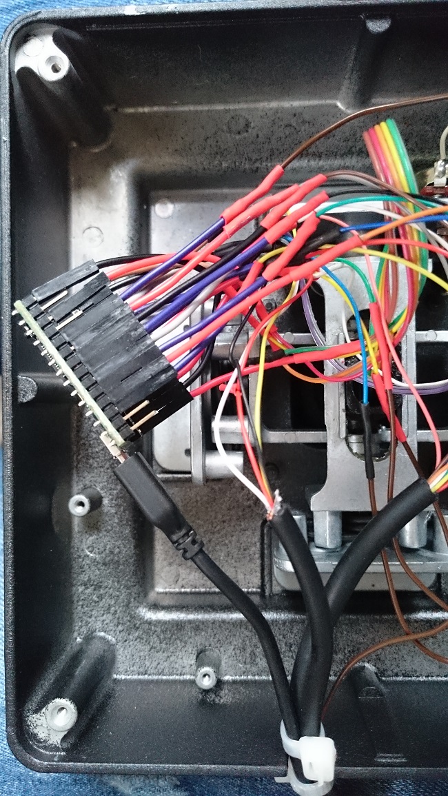
This gave me 11 lines to be brought over to the Teensy in the Joystick. The now unused gameport cable on the throttle has 10 lines, so I would need to use another cable. Once cabled up, I connected the read lines to pins 0 - 7 and the three SEL lines to pins 18, 19&20.
Once all of this was soldered up, I wrote a small sketch to try to read the buttons. After a number of iterations, and a very informative email from the author of the aforementioned page, I had a working sketch… well almost. It turns out that when a line is brought HIGH or LOW, it takes a very small period of time to happen, so I had to add a very short;delay();call to provide the necessary time. Incidentally, to read a column, the SEL line must be taken LOW and;digitalRead();will return 0 for the activated buttons. See the sketch here…
Throttle-Analyse Sketch const int row[8] = { 0,1,2,3,4,5,6,7 }; // 2-dimensional array of column pin numbers: const int col[3] = { 18,19,20 }; // setup() runs once on boot void setup() { ;;; Serial.begin(9600); ;;; delay(2000); ;;; Serial.println(SFS Throttle Button analyser); ;;; delay(1000); ;;; for (int x = 0; x < 3; x++) { ;;; ;;; pinMode(col[x], OUTPUT); ;;; } ;;; delay(1000); ;;; for (int x = 0; x < 8; x++) { ;;; ;;; pinMode(row[x], INPUT_PULLUP); ;;; } }
void loop() { ;;; digitalWrite(col[0], 0); ;;; digitalWrite(col[1], 1); ;;; digitalWrite(col[2], 1); ;;; delay(10); ;;; for (int y = 0; y < 4; y++) { // only 4 buttons on this column ;;; ;;; if (digitalRead(row[y])==0) { ;;;;;;; ;;; Serial.println(y+1); ;;; ;;; };;;; ;;; } ;;; digitalWrite(col[0], 1); ;;; digitalWrite(col[1], 0); ;;; digitalWrite(col[2], 1); ;;; delay(10); ;;; for (int y = 0; y < 8; y++) { ;;; ;;; if (digitalRead(row[y])==0) { ;;; ;;; ;;; Serial.println(y+9); ;;; ;;; } ;;; } ;;; digitalWrite(col[0], 1); ;;; digitalWrite(col[1], 1); ;;; digitalWrite(col[2], 0); ;;; delay(10); ;;; for (int y = 0; y < 8; y++) { ;;; ;;; if (digitalRead(row[y])==0) { ;;;;;;; ;;; Serial.println(y+17); ;;; ;;; } ;;; } }
Once I had reliable reads, I integrated the code from this sketch into the main F22-SFS sketch, along with proper state-change handling for the buttons. This code can be found here:;https://github.com/gerryk/USBJoystick/tree/master/f22-sfs