Homebrewing an Off-centre Fed Dipole
During HF field day 2010, I had occasion to get some experience with the off-centre fed dipole, in this case, a commercially made unit from Buckmaster. Prior to this, I had heard that OCF dipoles ‘are a compromise’, ‘are noisy’, ‘are deaf’, ‘have wildly varying radiation patterns’ and many other negative comments. During field-day, our experiences definitely gave me cause to doubt the nay-sayers.
Around this time, I moved to a new house, and as always, part of moving involves planning out the new antennas. In my situation, the property is long and narrow, and has a number of medium-tall trees (> 50ft). The house, however, is at one end of the property, and, while there are trees located such that an antenna would be oriented broadside slightly north of west, having any balanced antenna, such as a multiband dipole or doublet, would have the feedpoint quite a distance from the house, and would definitely push the ‘untidy wires’ beyond the XYL acceptance threshold.
With this in mind, and using Google Maps, I modelled a few potential candidates for OCF installation. By the grace of the RF gods, there two of the taller trees are oriented almost perfectly, and with the short end of the OCF dipole beside the house, have the feedpoint within 20’ of the house, thus removing the need for ugly, and loss inducing, long runs of feeder.
I have an aversion to purchasing what can be made oneself, especially where the making is also an education. As a result, I did some investigation into what designs would give the best performance, along with longevity and cost factors being considered. The result was a 4:1 current balun consisting of two 1:1 baluns wound onto 3 inch mix 43 toroids, with two legs made from hard-drawn copper. The legs were to be cut for 80m, at a ratio of 2:1, giving leg lengths of ~90’ and 45’.
Studies done by John, EI1EM, confirmed that building my own balun would be a far preferable course of action compared to purchasing one. John has a number of wonderful toys for doing all sorts of analysis on RF systems, including a mRS MiniVNA, which generates high quality plots of frequency response, SWR, loss and so on.
John did an analysis on a number of baluns, from the barely affordable to the inexpensive. This analysis was quite revealing in terms of the varying quality of baluns commercially available. Loss figures on the edges of the HF bands varied from <1dB to >5dB for baluns sold as ‘broadband’ or ‘HF’. SWR also varied from as little as 1.3:1 on the edges to as much as 2:1, and sometimes increasing to well beyond 3:1 around topband.
The baluns that came out on top were expensive, and generally unavailable locally, thus necessitating the further expense of shipping from the US, and the likely possibility of a VAT and duty levy. More justification for a home-brew.
I started by winding two toroids bifilar. I used 14swg enamelled copper wire for the windings.
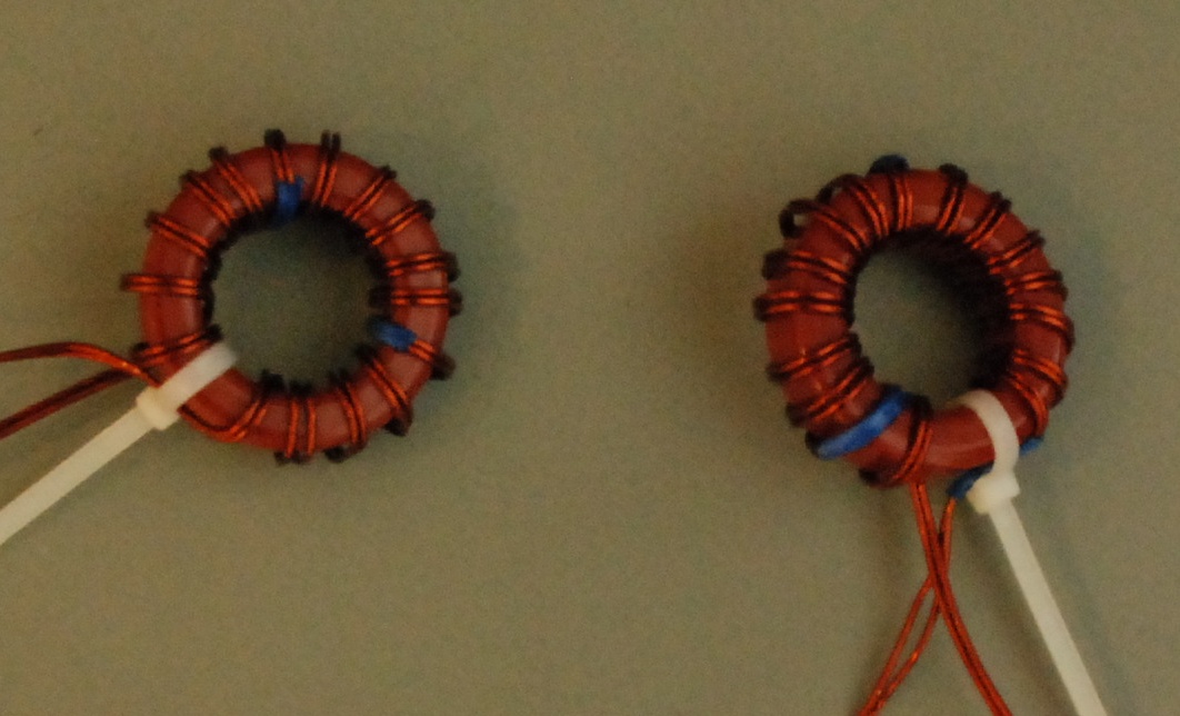
I tested these, and found that they exhibited a lower characteristic impedance than was required. I needed ~100ohm, and these were about 60ohms. So, I tried again, but with a wider spacing between the wires. This spacing could be provided by using insulated wire, so using 1.5mm2 domestic wiring, I rewound…
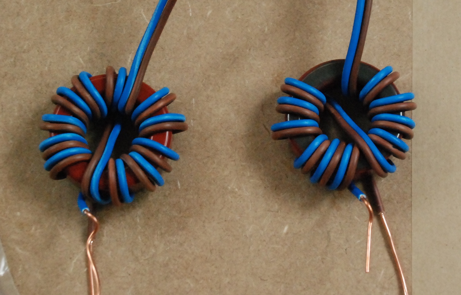
This time, the impedance matched what it should, being slightly short of 100ohms. The next stage was to connect the two 1:1 baluns back to back, giving a 4:1 balun, with an input impedance of ~200ohms and an output impedance of the familiar 50ohms.
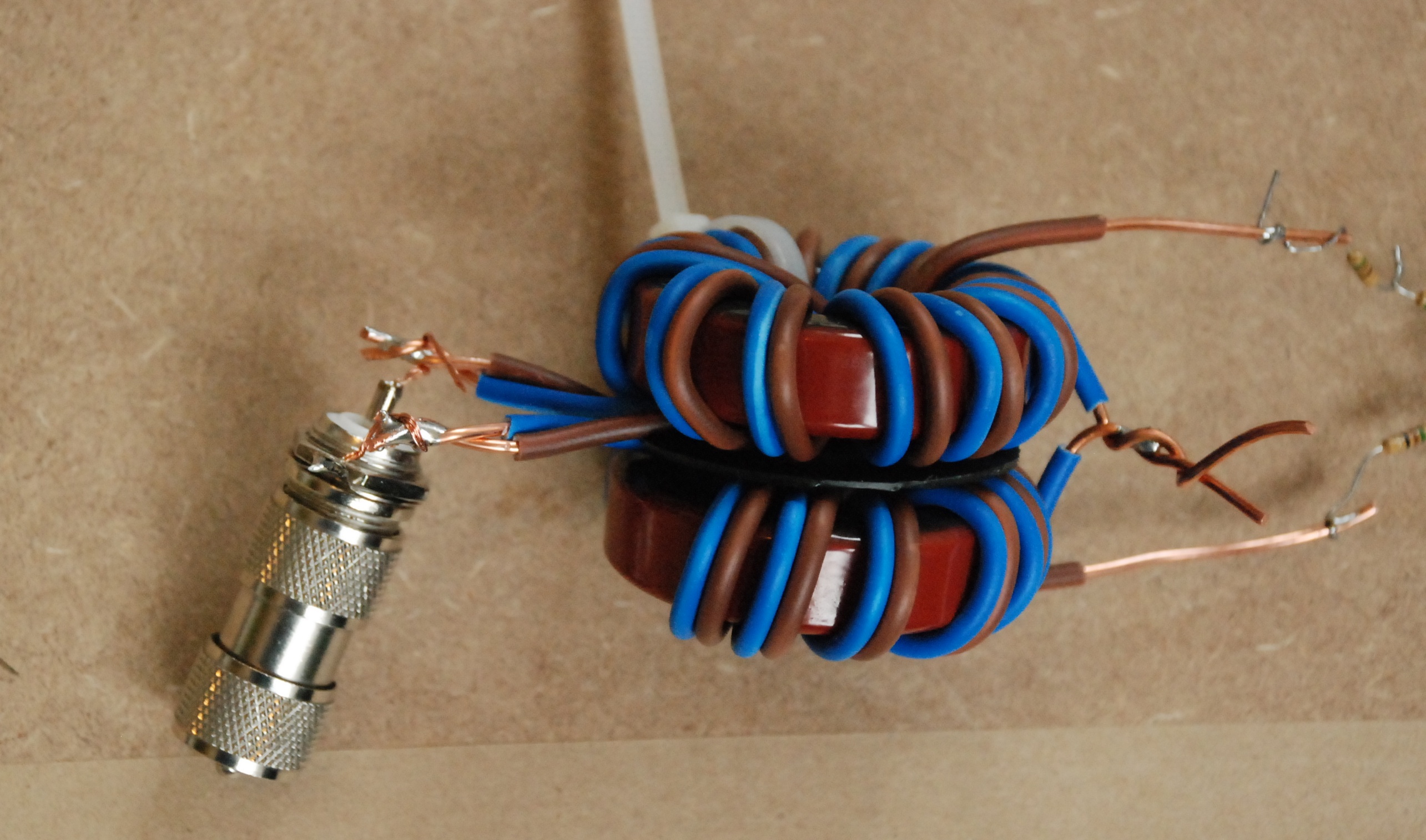
Four 50ohm resistors in series at one end, and the MFJ 259b Antenna Analyser on the other gives preliminary SWR of 1.1:1 across almost all of the HF band, rising slightly to 1.3:1 at the lower bounds of 1.5MHz. An encouraging start.
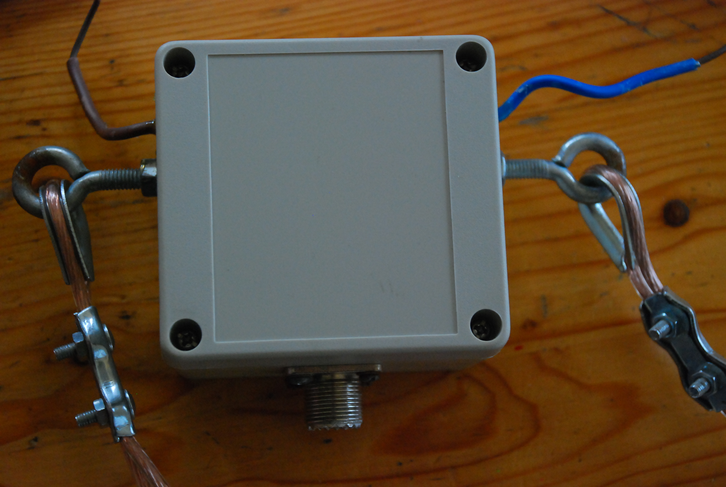
Mounting the entire assembly in a waterproof (IP40) case was a relatively straightforward operation. I drilled mounting holes for galvanised eyes, and a further one for the antenna socket (SO239). I also drilled two holes for pigtails to allow the antenna legs to connect to the balun.
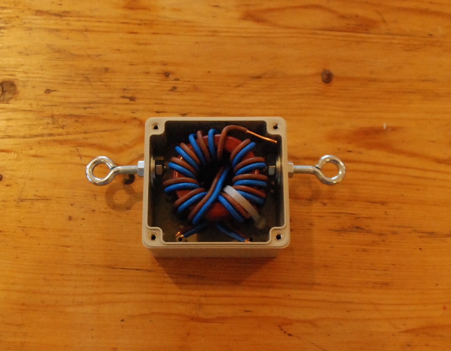
Once this was all done, I attached two legs, cut from hard-drawn copper, and cut roughly to a 2:1 ratio, as per standard OCF dipole design, and proceeded to fine-tune the lengths. After a bit of pruning, I got an acceptable SWR on 80m, 40m, 20m, 15m add 10m, with a surprisingly low 2.1:1 on 6m also. The maximum SWR was 2.3:1 on 20m, but I figured that the internal ATU in the IC756 ProIII would tweak that out.
On testing, I arrived at the conclusion that the antenna as installed at about 45’ was both sensitive and quiet. I also got a number of satisfactory reports on 80m and 40m, so I deemed the construction a success.
However, things are never as simple as they first appear. I was feeding the antenna with 30m of RG213, with the last 10 or so meters suspended from the feedpoint. This, coupled with the heavy balun caused the feedpoint to remain relatively static while the rest of the antenna moved around in the breeze. By itself, not a huge problem, but when coupled with the wild winds of the West, caused my new antenna to last about a month, before landing on the roof, one leg having broken right at the feedpoint, presumably having been work-hardened from the continued oscillation.
Not quite back to the drawing-board, but certainly some of the failings of the antenna had to be addressed. The first replacement was the antenna legs. Discarding the hard-drawn copper for something a bit stronger and more resilient, I splashed out on 50m of PVC coated flexweave. Not cheap, but I expected that this would be a bit more long-lasting than the previous effort. The next item to be swapped out was the feedline. Instead of the heavy RG213, I used a similar weight of RG8X, which is much smaller in diameter and weight, but more flexible, and not much more lossy.
I also replaced the terminators with heaver-duty units purchased from the hardware shop, giving a more flexible, but much sturdier connection to the balun eyes from the antenna legs.
I re-hoisted and retuned the antenna, with the help of Steve, EI5DD, who devoted a Saturday to the effort, and by afternoon, we had the antenna up and tuned. This time, we took even more time in the pruning operation, and as such, achieved <2:1 SWR on almost all bands.
That was a few months back, and to date, despite the best efforts of some Springtime gales the antenna is still up. I have since added weighted bungee cords to the ends of the hoisting ropes to add even more flexibility to the system, and help prevent the Galway weather taking its toll too much.