Raspberry Pi Wobbulator
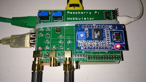
I came across am interesting project at the;Mayo Radio Experimenter’s Club;Rally;earlier this year.;A Wobbulator. A small board that would piggy-back on a Raspberry Pi and utilise an Analog Devices AD9850 Direct Digital Synthesiser as an RF source. ;The purpose of a Wobbulator is to generate an RF sweep which can be routed through a device undet test, and captured, in this case, using an RF-voltmeter, but traditionally using an oscilloscope, to determine the characteristics of the device to be tested. It can be used to determine the response of filters and crystals and other RF circuits. A Wobbulator would, in the past, have cost hundreds of euros, so to see;the full kit;available for a Rally special price of €40 was all the excuse I needed to get one. I already have a few Raspberry Pis and had a DDS on the way from eBay, so no further expenditure would be needed. The kit included a well manufactured board and all the various parts, including some header strips to connect to the GPIO array on the Pi and some high quality SMA ports for the RF in and outputs.;
The assembly started out with soldering some SMD devices… a few capacitors, diodes and resistors and two 1mm pitch DIL chips. I used a .5mm tip on my iron and .3mm silver bearing solder to mount these. I tinned the pads on the board first, then using a fine tweezers, held each device while I flowed to one side, and then other. The chips were a little more tricky, keeping all of the legs aligned while tacking one corner and then the other. The rest of the components are through-holeand a relatively trivial install. A set of headers are installed to take the DDS, and a double header on the other side to connect to the Pi.
Once assembled, I started with a basic install of Rasbian on an SD card. A few tweaks need to be done to enable the functionality of the Wobbulator, and install the Wobbulator control software.
The default configuration for Rasbian is that i2c is disabled. We need to re-enable this first.Edit;/etc/modprobe/raspi-blacklist.conf;and comment out the line that blacklists i2c.
blacklist spi-bcm2708 #blacklist i2c-bcm2708 blacklist snd-soc-pcm512x blacklist snd-soc-wm8804
Then edit;/etc/modules;and add a line to load;i2c-dev.
snd-bcm2835 i2c-dev ;
Install i2c-tools, add the ‘pi’ user to the ‘i2c’ group and power-down the Pi.
$ sudo apt-get install i2c-tools $ sudo adduser pi i2c $ halt
While the Pi is powered-off, attach the Wobbulator board to the GPIO array and power up the Pi.
When it restarts, check that the Wobbulator has been detected.
$ i2cdetect -y 0 ; ; ;0 ;1 ;2 ;3 ;4 ;5 ;6 ;7 ;8 ;9 ;a ;b ;c ;d ;e ;f 00: ; ; ; ; ;– – – – – – – – – – – – – 10: – – – – – – – – – – – – – – – – 20: – – – – – – – – – – – – – – – – 30: – – – – – – – – – – – – – – – – 40: – – – – – – – – – – – – – – – – 50: – – – – – – – – – – – – – – – – 60: – – – – – – – – 68 – – – – – – – 70: – – – – – – – –
The ‘68’ indicates that the Wobbulator has been successfully detected. Next,;install the required Python libraries.
$ sudo su;
curl;https://bootstrap.pypa.io/ez_setup.py;-o - | python3
exit
$ git clone https://github.com/quick2wire/quick2wire-python-api.git $;cd quick2wire-python-api/ $ sudo python3 setup.py install; $ cd ~
Finally, install the Wobbulator software. $ git clone https://github.com/mi0iuo/RPi_Voltmeter.git $ git clone https://github.com/mi0iuo/RPi_Wobbulator.git
Once this is done, we need to test and calibrate the Wobbulator, as follows:
$ startx
Once LXDE has started, open a Terminal window and enter the following:
$ cd RPi_Voltmeter-master $ python3 rpi_voltmeter.py
A small window will display.
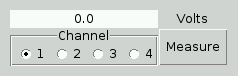
Leave Channel on channel 1, and click the Measure button. This will likely display a voltage up around 2v. This is around the maximum voltage the RF voltmeter can sample, so we need to reduce this greatly, since there is currently no input. On the board, there are two variable resistors (little blue boxes) with a little brass adjustment screw on each. Start to turn the one in the channel 1 section on the board anti-clockwise, clicking Measure periodically, until you get a voltage around 0.1v.
Do the same for Channel 2, except the target voltage is around 0.6v.
At this point, the Wobbulator is calibrated. You may exit the voltmeter and run the Wobbulator control software by entering the following in the Terminal:
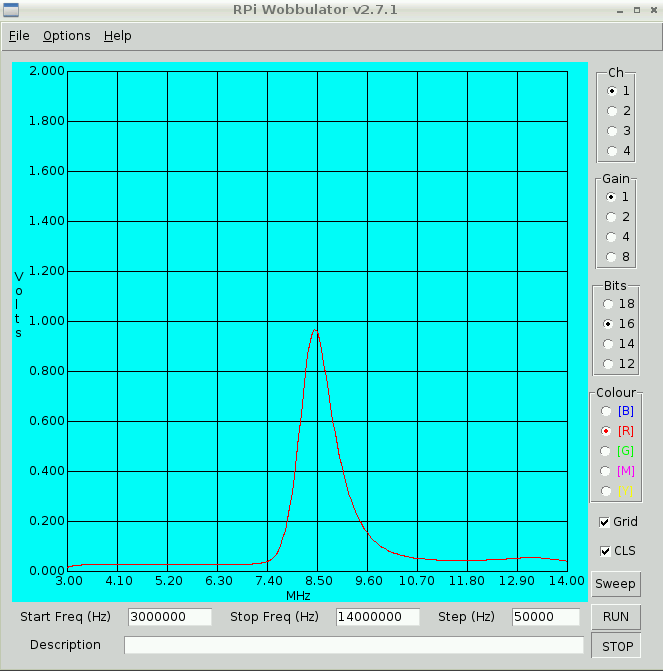
$ cd ../RPi_Wobbulator-master $ python3 rpi_wobbulator.py
Once this was done, I ran a quick test of a filter I had built a year or so ago. The results, while not what I wanted, were excellent. The trace showed the filter to be out by about 1MHz, so there are a couple of toroids to be rewound. I will use theMFJ 259b;with a ‘custom’ connector as an L/C meter to verify the toroids. I will document this process in another post.